1.放電取得実験 (Discharge) - DIS (メインミッション)
DIS = On-board oscilloscope (OBO) + Arc vision camera (AVC )
【Objective】
Acquire current waveform and image of arcing phenomena on high voltage solar array → If executed successfully, it will be a world premiere!
放電取得実験(DIS)=オンボードオシロスコープ(OBO)+放電火花撮影カメラ(AVC)
【目的】
宇宙空間において、太陽電池アレイ表面での放電電流波形を計測し、放電画像を取得して発生箇所を特定する⇒ 世界ではじめて!
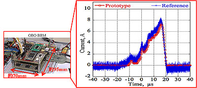
*On-board oscilloscope (OBO) current waveform comparison with "ground-based" oscilloscope
2.放電抑制実験 (High voltage solar array) - HVSA
【Objective】
Generate high voltage to induce a 300V or higher potential difference between solar array surface (triple junction type) and the surrounding plasma to study discharges and their possible mitigation techniques
【目的】
低軌道プラズマに対して300V以上の負電位をもった太陽電池アレイでの放電を抑制する手法(フィルムアレイとコーティングアレイ)について、軌道上実証を行う

*Special spherical solar cells to generate 300V
3.放電劣化実験 (Solar cells performance degradation due to arcing)-DEG
【Objective】
Evaluate discharge mitigation performance of either filmed or coated triple junction solar cells
【目的】
新たなデザイン「コーティングとフィルム」によって太陽電池アレイの放電を抑制できるかを検証する
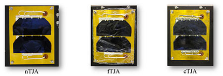
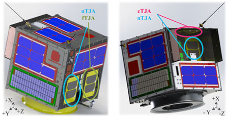
*nTJA:nominal triple junction solar cells - 通常型太陽電池
*fTJA:filmed triple junction solar cells - フィルム型太陽電池
*cTJA:coated triple junction solar cells - コーティング型太陽電池
4.プラズマ密度計測 (Double Langmuir probe) - DLP
4.1 Purpose
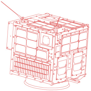
The Double Langmuir Probe (DLP) Misson of HORYU-IV Satellite is a novel plasma measurement system designed and developed at the Laboratory for Spacecraft Environment Interaction Engineering (LaSEINE) at Kyutech. This mission applies the principle of Langmuir Probe which operates by inserting one or more electrodes into plasma, with a constant or time-varying electric potential between the various electrodes or between them and the surrounding vessel. For this system, a varying voltage is applied between two probes LP+ and LP- and measurement system records this voltage and the current as a result to measure plasma parameters (temperature, density, and plasma potential) at the orbit of HORYU-IV satellite (575km, 31deg). This mission shall contribute to the characterization of discharge on solar panels due to high voltage in space with respect to plasma condition.
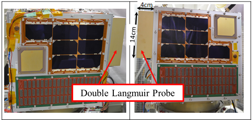
Figure 1 FM of HORYU-IV satellite showing location of DLP in +Y and -Y directions (gold plated PCB of 4cm×14cm)
After several ground validation tests and consideration of design specifications such as operability of the plasma measurement system in LEO grade plasma, mitigation of probes contamination in space and sputtering of probes surface in space it was confirmed that this plasma measurement mission could measure the plasma electron density in the range of 10^10 to 10^12 m-3 which is appropriate for HORYU-IV satellite orbit.
4.2 System Description
Figure 2 shows the DLP system which consists of probe biasing circuit, the analog measurement circuit, and the controlling electronics. The probe biasing circuit is controlled by ON and OFF signals from the Big Apple microcontroller. The system has 5 switches that perform 3 main functions: capacitor discharge, DLP mission, and probe cleaning. This system is isolated form the satellite bus through an OpAmp isolator. 5 photo MOSFET switches are used to accomplish 3 sets of controlling tasks: 1 switch for capacitor discharge, 2 switches for mission, and 2 switches for probe cleaning. The photo MOSFET switch is a solid state relay which consists of a light-emitting diode (LED) for the input side and MOSFETs for the contact point. It is not only smaller and lighter, but also easier to drive and faster than conventional mechanical relays.
Any of the 3 types of signals from the Big Apple microcontroller (capacitor discharge, mission, and probe cleaning) causes a forward current to flow through the photo MOSFET.
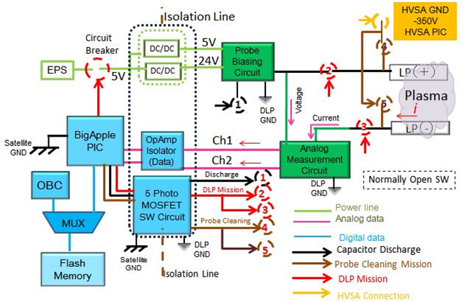
Figure 2 DLP system overview
The DLP electronic is located on an electronic board called the Big Apple board as shown in Figure 3. This board also has 3 other missions: vacuum arc thruster mission (VAT), photo-electrons current measurement mission (PEC), electron-emitting film (ELF)/surface charging monitor (SCM) mission. These four missions share a microcontroller that controls the operations, how power is distributed, and how data are saved. The Big Apple microcontroller receives command from the on-board computer (OBC) to carry out any of the four missions and also to downlink missions data. The power to this board is a 5V supply from the electric power system (EPS).
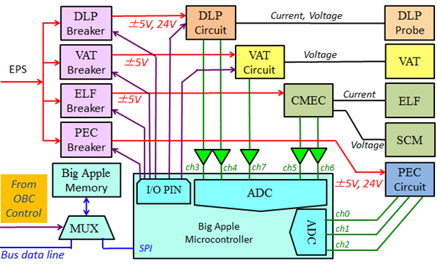
Figure 3 Big Apple mission board
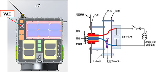
5.真空アークスラスター (Vacuum arc thruster) - VAT
【Objective】
On-orbit demonstration of a trigger-less vacuum arc thruster, which circuit is directly connected to the high voltage solar array
【目的】
高電圧太陽電池アレイ(300V以上)に昇圧回路を介さずに、直結した真空アークスラスターの軌道上実証を行う
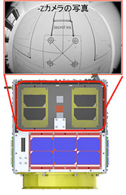
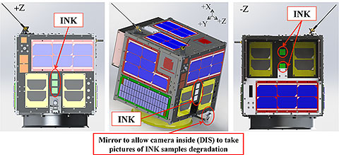
6.あぶり出し (Secret ink) - INK
【Objective】
Study of surface degradation by atomic oxygen
【目的】
高分子フィルムの宇宙空間での劣化について、フィルム下におかれた銀面の酸化(黒色化)をカメラで検知して検証する
7.光電子電流計測 (Photo-electrons current measurement) - PEC
7.1 Purpose
Photo-electrons current is one of the major sources contributing to spacecraft charging. This mission objective is to measure photo-electrons current as a consequence of spacecraft charging. PEC mission development aimed at establishing a current amplifier able to measure currents of the order of nano-Ampere (nA) from metallic and insulator surfaces using the AM0 spectrum.
This mission is based on the principle of photoelectric effect in which the energy carried in a photon is transmitted to an electron in the surface of a material. The electron absorbs the photon’s energy and is displaced from the surfaces of the material, thereby creating a small electric current. A current-voltage amplifier circuit is then used for amplification of this current and data collection using a PC. On-board HORYU-IV, 3 different materials are mounted for photo-electrons current measurement: Gold, KaptonR (polyimide), and Black KaptonR. Figure 1 describes the mission details.
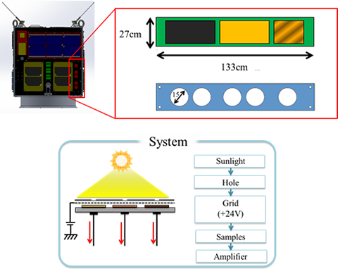
Figure 1 On-orbit measurement of photo-electrons current
This mission is necessary to estimate the photo-electrons emission current influence on spacecraft charging and therefore discharge phenomenon. This will help to predict the electric properties of various materials irradiated by sunlight. Thanks to the collected data, for a given application, the most suitable materials could be determined during a spacecraft design phase.
7.2 System Description
PEC system is a current-voltage amplifier circuit that consist of LMC6001 ultra-low input operational amplifier, MCP6032SN operational amplifier, capacitors, resistors, and others discrete components. This circuit is designed to have three sub-circuits mounted on a single board for measurement of each sample output photo-electrons current.
This circuit was designed with Easily Applicable Graphical Layout Editor (EAGLE) software and the components were located on the printed board as defined in the circuit diagram and then soldered. Figure 2 shows the schematic diagram of PEC system.
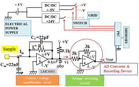
Figure 2 PEC measurement system schematic
The PEC system is connected to the Big Apple board that serves as an interface to PEC mission execution. The sequence of operations is as follows: 1) on-board computer (OBC) writes command to Big Apple flash memory; 2) Big Apple microcontroller reads the command from Big Apple flash memory and closes 5V switch to provide the adequate power to PEC; 3) if sun sensors measurements provided by the altitude and orbit determination system (AODS) show that the incident sunlight on the ?Z panel is within ±15deg, Big Apple microcontroller closes 24V switch to bias PEC grid; 4) mission starts; 5) after the mission ends, Big Apple microcontroller receives data from PEC, which are then written to Big Apple flash memory; 6) OBC reads PEC data through Big Apple flash memory prior to data transmission to a ground station.
8. 地球撮影 (Camera for Earth photography) - CAM
8.1 Mission Overview
The CAM sub-system is responsible for capturing Earth images. It is part of HORYU-IV’s project outreach activities to communicate with local and international communities.
8.2 Objectives
◇ To take images of the Earth
◇ To take images of the Earth at specified location
◇ To store images on its own memory for OBC to access and read. Images will be transmitted by COM sub-system to any ground station.
◇ To contribute to HORYU-IV’s outreach activities through Earth imaging.
8.3 CAM sub-system
The CAM sub-system is sharing PCB with AODS sub-system. The sub-system consists of the following: (1) a PCB board containing the electronics (Figure 1), (2) two camera modules (Figure 2) mounted on satellite Y panels, and (3) camera modules’ harness (Figure 3).
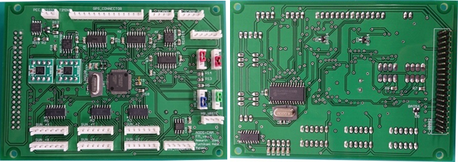
Figure 1 AODS/CAM board
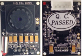
Figure 2 C1098 camera module
(front and back sides)
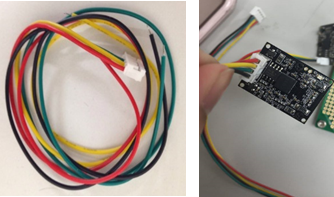
Figure 3 Camera module harness
The C1098 is a JPEG compressed still camera. When the snapshot command is sends from the host, the camera module capture a full resolution single-frame still picture. The picture is then compressed by JPEG engine and transferred to the host thru serial interface. The C1098 is small in size, 20mm×28mm. The focal length is 4.0m and field-of-view (FOV) of 64 degrees. It features VGA resolution and can be down sample to QVGA. It is a low power device and operates at 3.3V.
8.4 CAM Modes of Operation
Essentially, there are 3 main modes of operation:
a) Timer Mode ? Start at time t specified by the OBC. On timer signal, it shoots an image or several images and saves to flash memory.
b) Normal Mode ? CAM take one picture of the Earth at a time using AODS data. If the image taken is not in space, the data will be saved to flash memory.
c) Target Mode ? Reads the GPS data, compare the longitude and latitude with data received by OBC. Then take the number of images at specified time interval. Images are saved to memory.
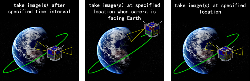
Figure 4 CAM modes of operation. Timer mode (left), normal mode (middle), target mode (right)
8.5 CAM Schematic Diagram
The block diagram is shown in Figure 5.
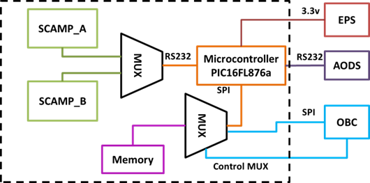
Figure 5 CAM system block diagram
The CAM starts operating when switched ON by reading the command saved by OBC to CAM-memory. Depending on the command type and parameters, CAM reads the GPS data via Rx serial line connected to AODS sub-system. CAM executes its mission and save images data to CAM’s 8Mbit flash memory. OBC then accesses and reads information on CAM’s flash memory and transmits it to any ground station via COM. CAM PIC erases CAM flash memory (all sectors) every time a new command is received from OBC H8 Main.
9.デジシンガー (Digi-singer) - SNG
【Objective】
Use the vocal synthesizer on board the satellite to send songs from HORYU-IV to the ground using UHF for space education purpose【目的】
衛星に搭載されたVocal Synthesizerを使って衛星から地上に向けてUHF電波を使って音楽配信する