1.構造系(Structure)
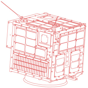
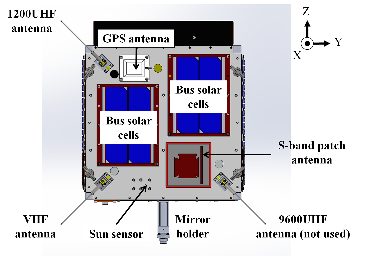
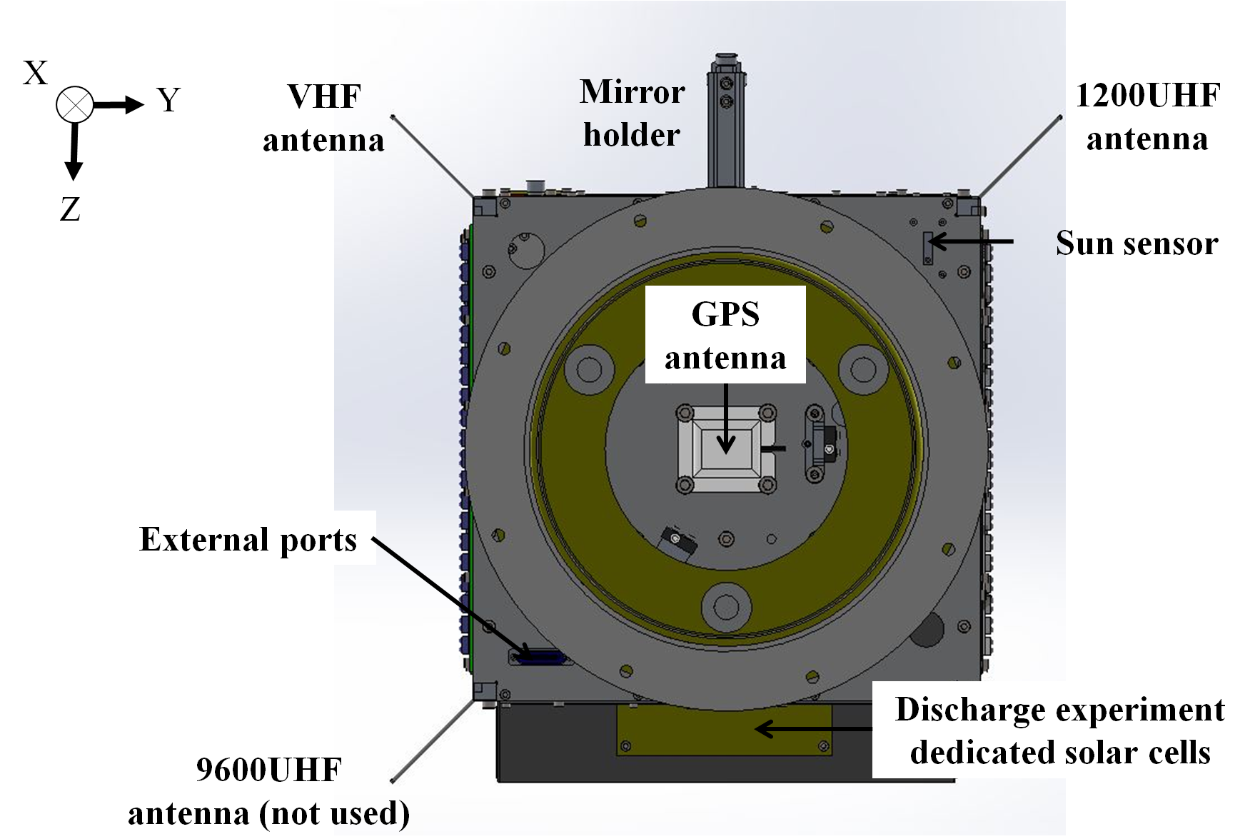
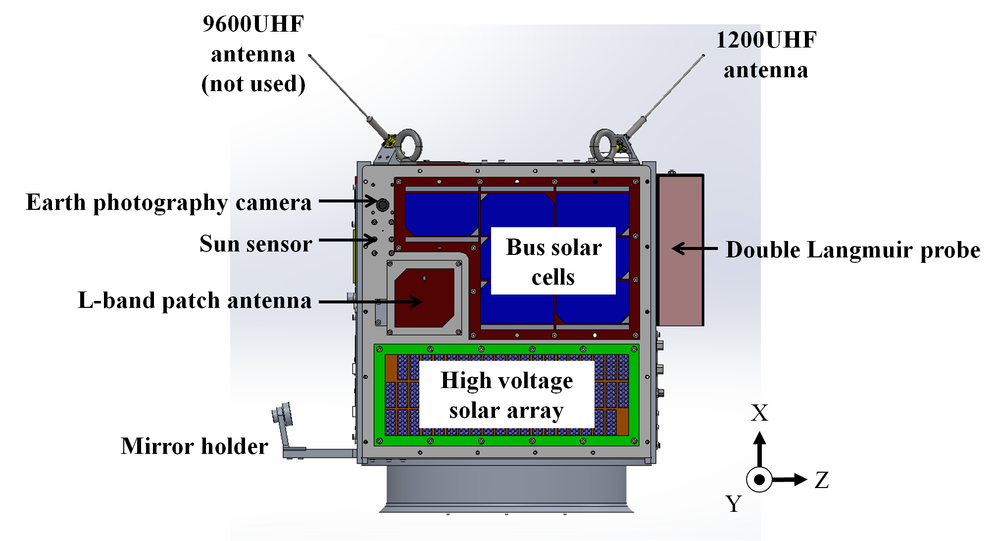
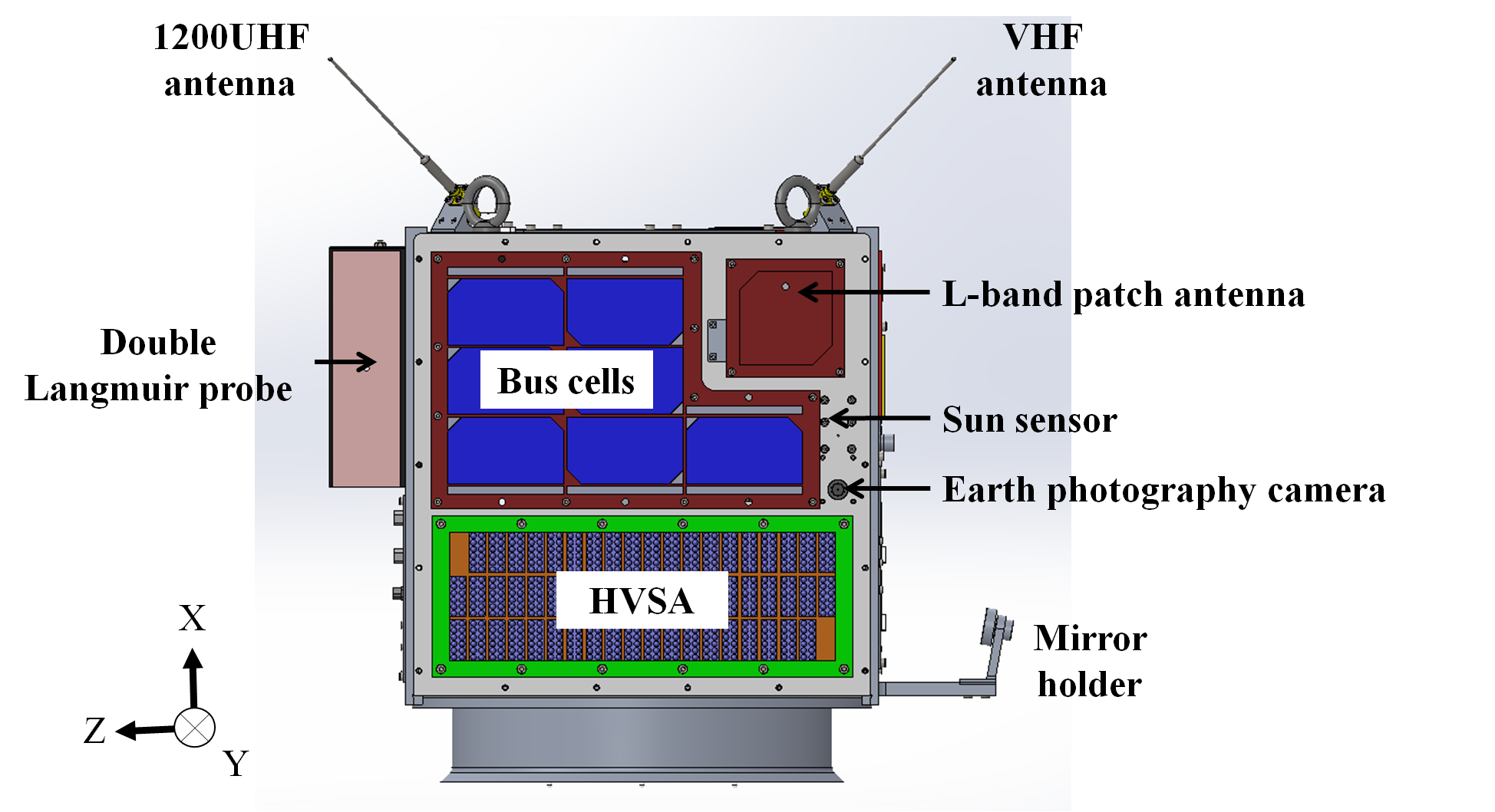
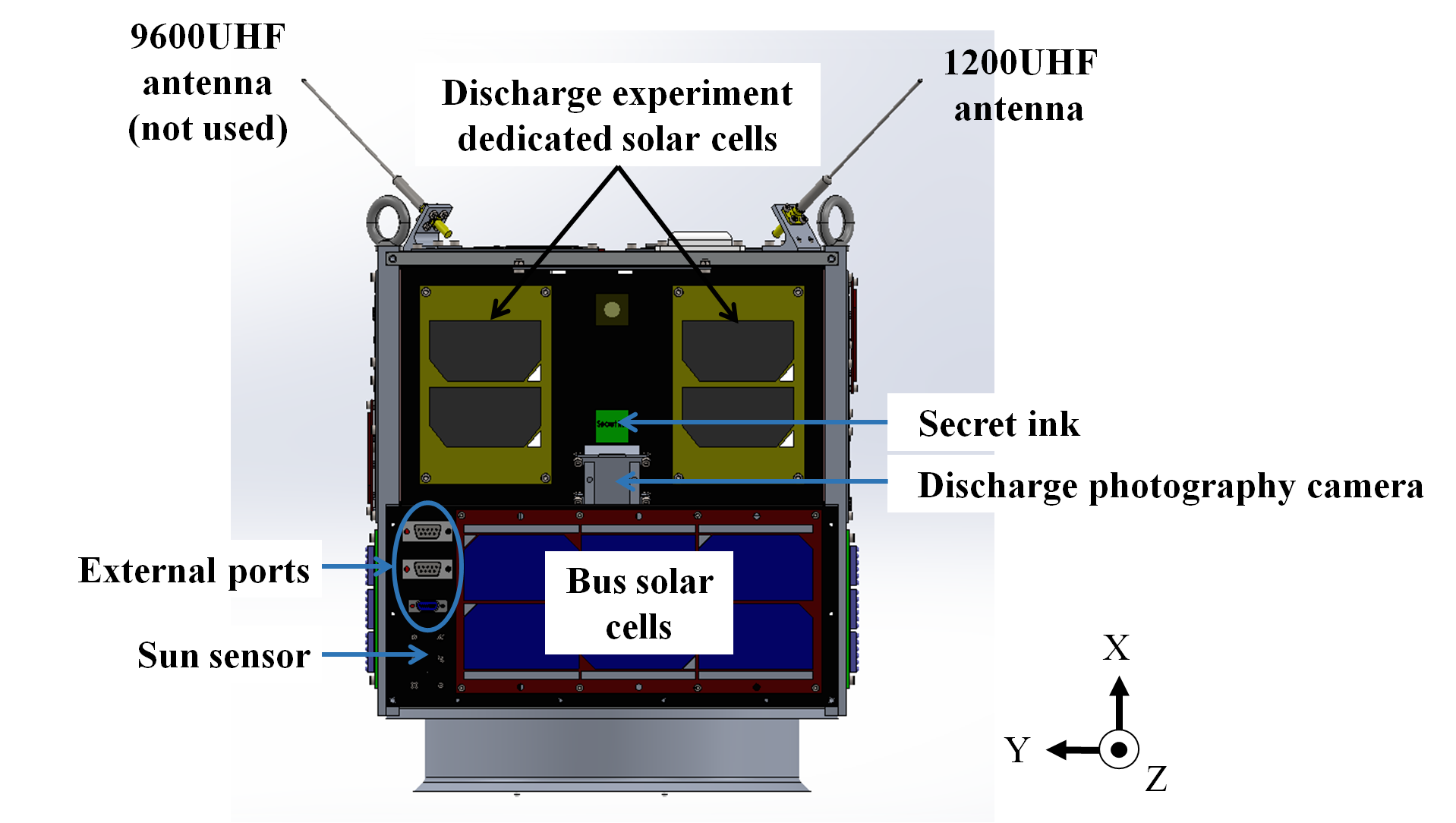
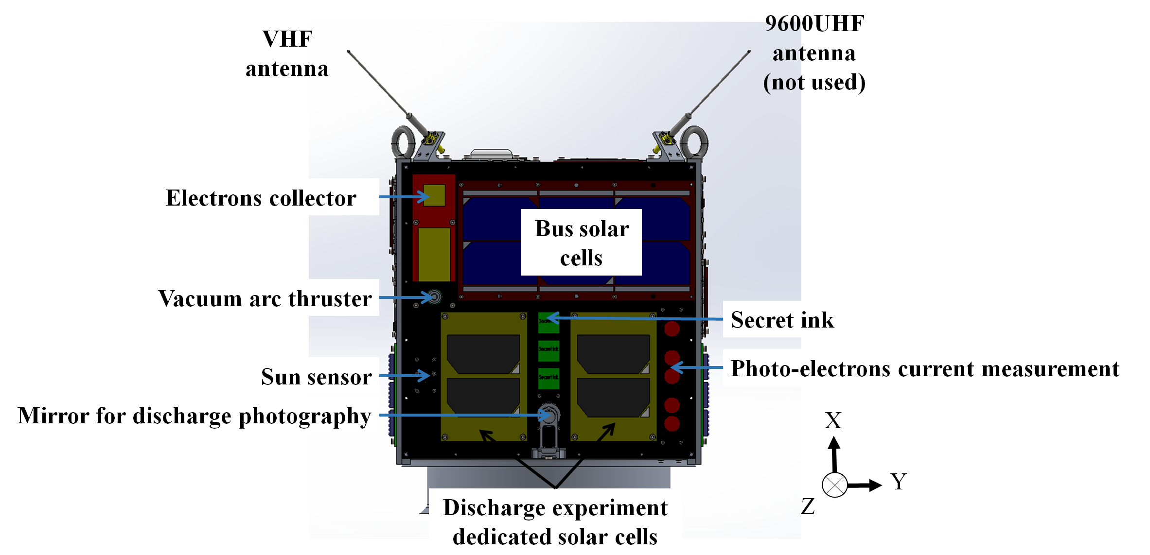
HORYU-IV is a cubic shaped nano-satellite, which external dimensions are (H)450mm×(W)420mm×(D)430mm for a total weight of 10kg approximately.
The UHF antennas, the VHF antenna, and the arm holding the mirror are fixed, which makes HORYU-IV a deployment-free nano-satellite.
The structure shall accommodate the 9 missions carried on-board HORYU-IV and the figures below show their arrangement.
2.熱制御系 (Thermal Control)
1. Thermal Control Overview
On spacecraft, most active equipment can only work at room temperatures. For batteries, the acceptable temperature range is from 0oC to 45oC. More generally, as a rule of thumb, the life-span and reliability of any semiconductor device is inversely proportional to the junction temperature. Thermal control (TC) is vital in any active system, and TC failure may be catastrophic. For example in HORYU-IV case, if the satellite or its components undergo too cold or too high temperatures, missions could fail to be executed or received data could be biased, which would affect the scientific value of the satellite.
Thermal control system (TCS) ensures that HORYU-IV will stay within an acceptable temperature range to allow missions to be properly executed.
2. Objectives
During the whole satellite life, the TCS must keep all the components within their respective temperature limits (very narrow) against the hostile thermal environment, such as the absence of convection, direct solar radiation, cryogenic space, on board energy dissipation.
Briefly, spacecraft thermal design has two main objectives:
- Prevent overheating. By carefully designing HORYU-IV structure and arranging the different parts to allow energy dissipation, the critical elements can be protected from overheating.
- Prevent overcooling. Using heaters, parts that are sensitive to cold temperatures can be heated upon command reception. For HORYU-IV case, the most critical elements to protect against cold temperatures are the batteries and there are two heaters to make sure they stay within their operational range.
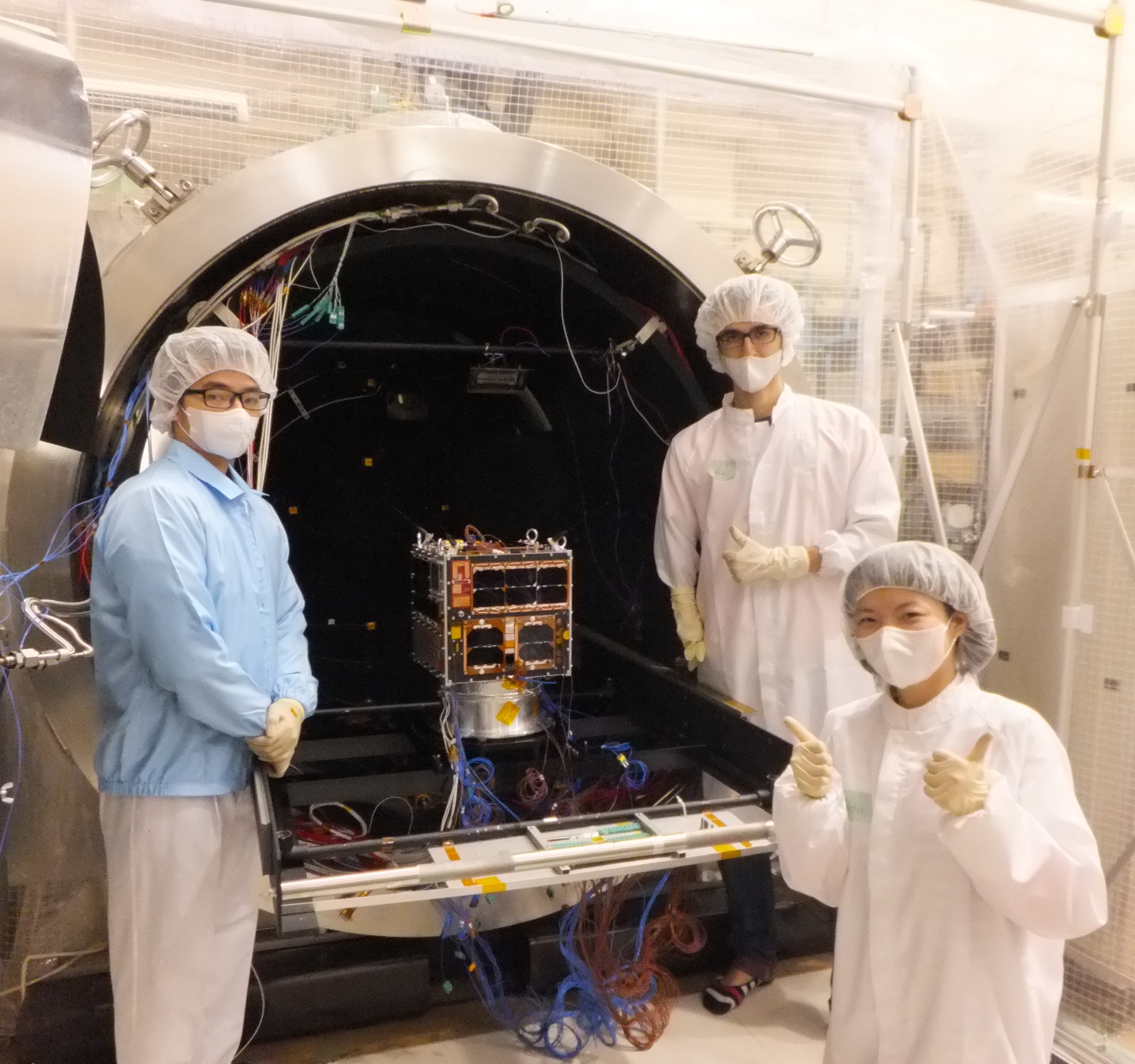
To guarantee that the objectives of the TCS will be met, an iterative procedure was followed. First, hardware specifications were assumed to find the corresponding temperature field. Then, assumptions were changed until an acceptable result is achieved. The iterative process included both simulation using Thermal Desktop software and testing such as thermal cycles and thermal vacuum.
The design of HORYU-IV thermal control system does not end with ground design and verification, but it will continue during the whole satellite life through operational tele-monitoring and tele-control. In total, there are 17 temperature sensors (LM35) that are mounted to the satellite to provide regular information on the thermal behavior of the different components.
Thermal and structure team before FM thermal vacuum test
3.オンボードコンピュータ系 (On-Board Computer, OBC)
OBC is the brain of HORYU-IV and it controls the nano-satellite functions such as starting・ending mission, store data, reset, and more… HORYU-IV uses three micro-processors: 2×Renesas H8 36057F and 1×PIC16F876A.
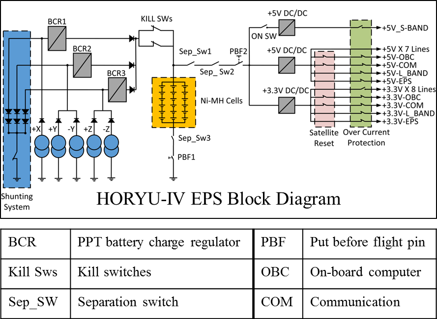
4.電源系(Electrical Power Supply, EPS)
Electrical Power Supply (EPS) is one of HORYU-IV bus sub-systems. The function of EPS is to provide uninterrupted power to all sub-systems during the satellite’s lifetime. High reliability, high efficiency, and simplicity are the main requirements that were considered in the design of EPS.
HORYU-IV EPS consists of solar arrays, rechargeable batteries, and Power Control and Distribution Unit (PCDU).The simple design and usage of available commercial off the shelf (COTS) components are the main features of PCDU, which controls the battery charging and load voltage regulation.
Here, Peak Power Tracking (PPT) topology was selected to extract maximum power generated by the solar arrays. The extra energy is stored in Nickel Metal Hydride (Ni-MH) batteries.
HORYU-IV is equipped with 34 triple junction solar cells able to generate at peak 9W and on average 5.2W. To sustain constant power generation during eclipses, HORYU-IV is equipped with 18 Ni-MH batteries (3 parallel sets of 6 batteries in series) able to provide 5700mAh at 7.2V.
5.姿勢系(Attitude and Orbit Determination System, AODS)
AODS (Attitude and Orbit Determination Sub-system) role is to determine the attitude and position on the orbit of HORYU-IV, as well as passively control its attitude.
To do so, HORYU-IV is equipped with six sun sensors (one mounted on each panel), one GPS with two antennas, two 3-axis gyro sensors, four permanent magnets and one hysteresis damper.
Most of the components of the sub-system are COTS (Commercial-Off-The-Shelf). AODS board, sun sensors and hysteresis damper were designed by Kyushu Institute of Technology.
A blog diagram of AODS and its relation with other missions and sub-systems is shown in Figure 1.
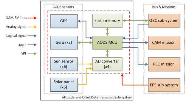
Figure 1 Block diagram of AODS and its relation with other missions and sub-systems
AODS is activated by OBC. Data transmission between the sub-systems is going through a flash memory. OBC can send the following commands and data to AODS: GPS turn ON/OFF, transmission data to CAM mission turn ON/OFF, use Gyro1 or Gyro2, change period of saving AODS data in the flash memory, set new parameters for Sun sensors.
AODS algorithm gives information for the CAM mission about the satellite position in or out of eclipse, pointing of any of the two cameras to the Earth, and latitude, longitude and time from GPS.
AODS sends a logical signal to PEC mission. The logical signal is +5V when a sun sensor from the same panel as PEC elements detects a sun with inclination ±15°. In other cases it is 0V.
Changing parameters of Sun Sensors from a ground station gives an opportunity to adjust theirs voltage levels and equation parameters and do onboard sensors calibration.
AODS sub-system and CAM mission are placed on the same PCB board. Figure 2 shows photos of the board.
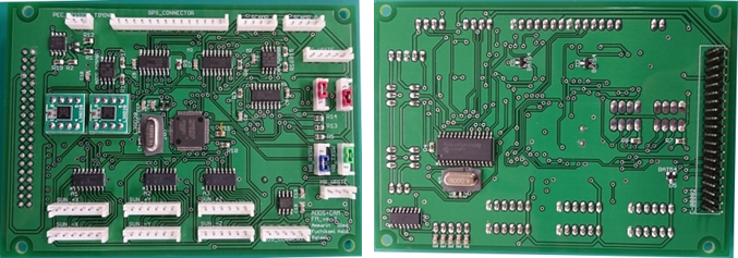
Figure 2 Photos of AODS/CAM board
6.通信系(Communication, COM)
COM purpose is to transmit telemetry from HORYU-IV to any Earth ground station, and receive commands from Kyushu Institute of Technology ground station.
HORYU-IV is equipped with one S-band transmitter (2400.3MHz), one UHF transmitter (437.375MHZ), one VHF receiver (145MHz), and one L-band receiver (1200MHz).
During normal operations, the S-band is used at 100kbps to transmit mission and telemetry data (BPSK modulation). In case S-band doesn't work properly, radio amateur frequency will be used through the 1200bpsUHF transmitter (AFSK modulation).
Housekeeping data (incl. EPS data, temperature, orientation, and sensors data) and satellite beacon are transmitted in Morse code (CW) at 20wpm.
Commands are received through the VHF antenna at 1200bps. In case VHF antenna doesn't work properly, reset command can be used through the L-band patch antenna (DTMF).
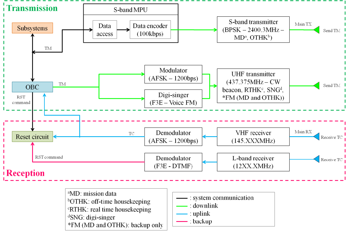
HORYU-IV communication diagram
7.地上局(Ground Station, GS)
Kyutech's GS is located at a latitude of 33deg53'28N, a longitude of 130deg50'26E, and an altitude of 47m above sea level.The GS is the interface between HORYU-IV and the end user.
It receives data from the satellite and transforms them to be easily seen and understood by the end-user, such as graphs, pictures, etc.To comply with COM systems on-board HORYU-IV, the GS is equipped with UHF/VHF antenna, S-band antenna, and L-band antenna.
Kyutech's GS antennas role and operation
| Antenna | Role | Operation |
|---|---|---|
| S-band (2400.3MHz) | Receive mission data at 100kbps | Primary |
| UHF | Receive CW data at 20WPM | Primary |
| UHF | Receive mission data at 1200bps | Backup |
| VHF | Send commands at 1200bps | Primary |
| L-band (1200MHz) | Send reset command using DTMF | Backup |
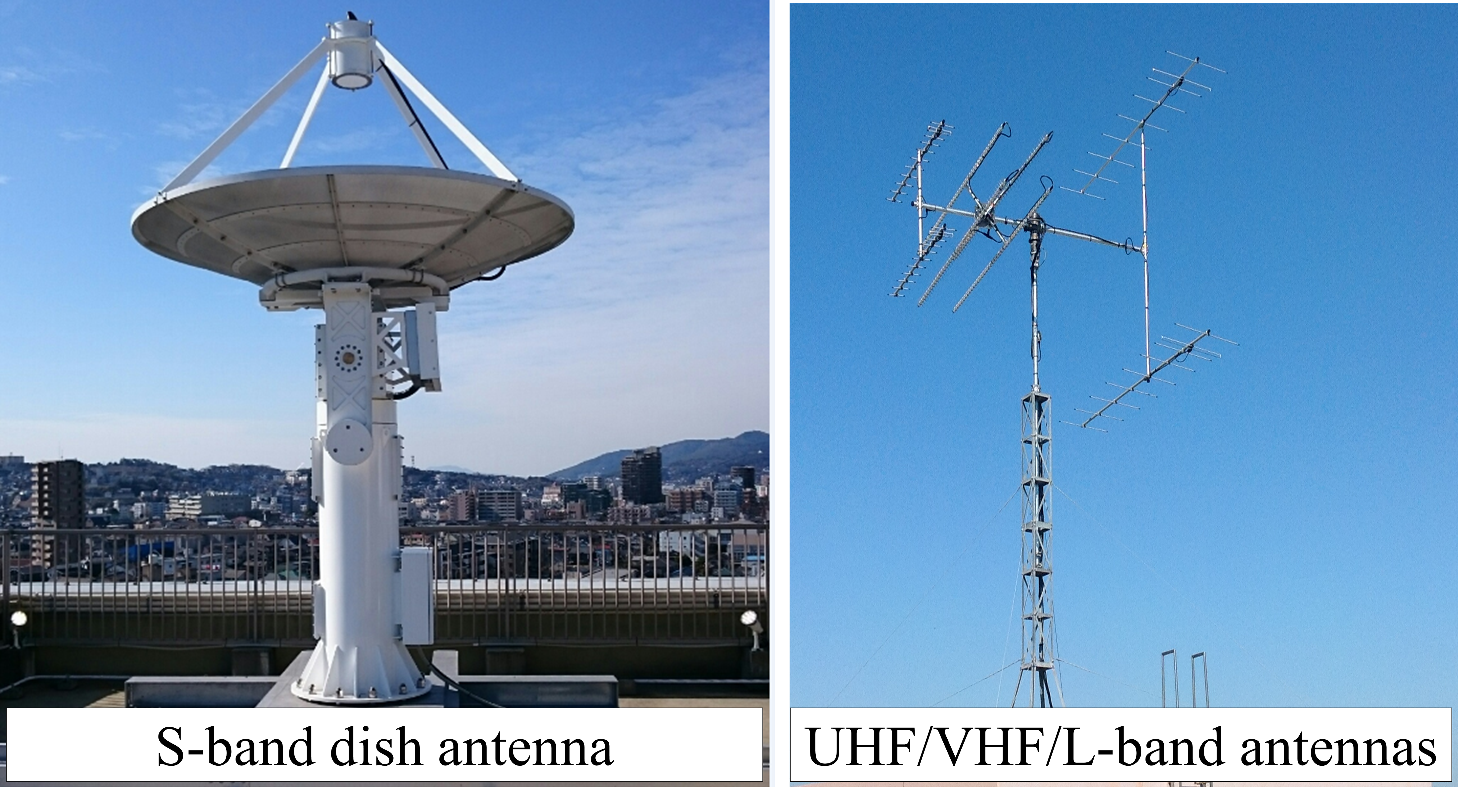
Kyutech's GS - S-band/UHF/VHF/L-band antennas
- Overall GS description (PDF):click here for details
- UHF, VHF, L-band GS description (PDF):click here for details
- S-band GS description (PDF):click here for details